Note
Click here to download the full example code
A full PyMAPDL example#
Let’s see a full PyMAPDL example!
We will reuse some of the code we used to plot the section of a NACA airfoil. With this section we will create a simple and straight wing where we will apply some constrains and loads.
The idea is you can have an idea on how to use PyMAPDL together with other Python libraries for your own purposes (TFG? TFM? PhD?)
Setting up the environment#
First, let’s do some imports
from matplotlib import pyplot as plt
import numpy as np

from ansys.mapdl.core import launch_mapdl
and let’s launch PyMAPDL.
mapdl = launch_mapdl()
mapdl.prep7()
*** MAPDL - ENGINEERING ANALYSIS SYSTEM  RELEASE                  22.2     ***
 Ansys Mechanical Enterprise
 00000000  VERSION=LINUX x64     10:48:52  OCT 03, 2022 CP=      4.017


          ***** MAPDL ANALYSIS DEFINITION (PREP7) *****
Geometry definition#
In the previous part of the talk we showed how to use some Python functions to plot a NACA airfoil. Here we will reuse those functions to generate the same section inside PyMAPDL.
# Helper functions
def camber_line(x, m, p, c):
    return np.where(
        (x >= 0) & (x <= (c * p)),
        m * (x / np.power(p, 2)) * (2.0 * p - (x / c)),
        m * ((c - x) / np.power(1 - p, 2)) * (1.0 + (x / c) - 2.0 * p),
    )


def dyc_over_dx(x, m, p, c):
    return np.where(
        (x >= 0) & (x <= (c * p)),
        ((2.0 * m) / np.power(p, 2)) * (p - x / c),
        ((2.0 * m) / np.power(1 - p, 2)) * (p - x / c),
    )


def thickness(x, t, c):
    term1 = 0.2969 * (np.sqrt(x / c))
    term2 = -0.1260 * (x / c)
    term3 = -0.3516 * np.power(x / c, 2)
    term4 = 0.2843 * np.power(x / c, 3)
    term5 = -0.1015 * np.power(x / c, 4)
    return 5 * t * c * (term1 + term2 + term3 + term4 + term5)


def naca4(x, m, p, t, c=1):
    dyc_dx = dyc_over_dx(x, m, p, c)
    th = np.arctan(dyc_dx)
    yt = thickness(x, t, c)
    yc = camber_line(x, m, p, c)

    # We are tuning a bit the output of this function to facilitate later processing.
    x = x - yt * np.sin(th)
    x = np.concatenate((x, x + yt * np.sin(th)), axis=0)

    y = yc + yt * np.cos(th)
    y = np.concatenate((y, yc - yt * np.cos(th)), axis=0)
    return x, y
NACA Parameters for naca2412
Generating NACA points for the section.
Generating keypoints#
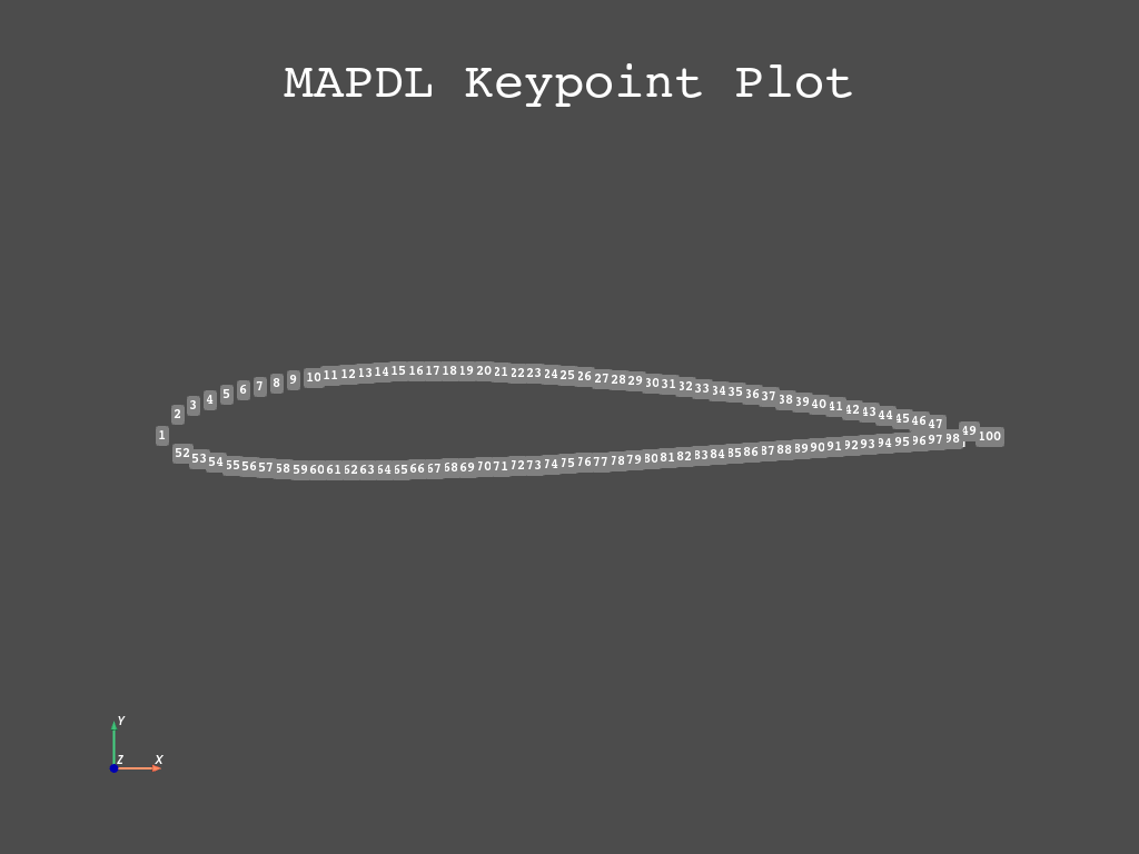
Checking results
pl = mapdl.kplot(return_plotter=True)
pl.view_xy()
pl.show()
Generate lines from the points#
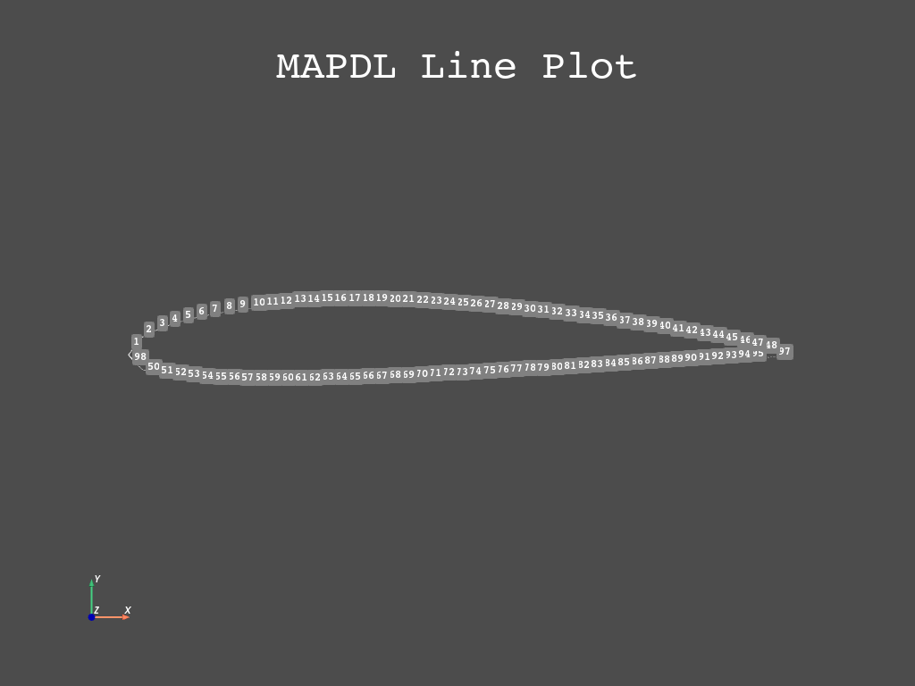
Because the helper functions give us two points per x-coordinate, we need to join those points in two times:
Closing the section
MERGE COINCIDENT NODES WITHIN TOLERANCE OF  0.50000E-01

 MERGE IDENTICAL MATERIALS WITHIN TOLERANCE OF  0.50000E-01

 MERGE IDENTICAL ELEMENT TYPES

 MERGE IDENTICAL REAL CONSTANT SETS WITHIN TOLERANCE OF  0.50000E-01

 MERGE IDENTICAL SECTION ID SET WITHIN TOLERANCE OF  0.50000E-01

 MERGE IDENTICAL ELEMENTS

 MERGE IDENTICAL COUPLED DOF SETS

 MERGE IDENTICAL CONSTRAINT EQUATIONS WITHIN TOLERANCE OF 0.50000E-01

 MERGE COINCIDENT KEYPOINTS WITHIN TOLERANCE OF  0.50000E-01

 *** WARNING ***                         CP =       4.177   TIME= 10:48:52
 Keypoints 1 and 2 cannot be merged because:
  (1) One or both of them belong to lines.
  (2) The distance between them ( 3.146864964E-02) exceeds the
  tolerance ( 3.146864964E-07).

 *** WARNING ***                         CP =       4.177   TIME= 10:48:52
 Keypoints 1 and 3 cannot be merged because:
  (1) One or both of them belong to lines.
  (2) The distance between them ( 5.248710857E-02) exceeds the
  tolerance ( 2.241384605E-07).

 *** WARNING ***                         CP =       4.178   TIME= 10:48:52
 Keypoints 4 and 5 cannot be merged because:
  (1) One or both of them belong to lines.
  (2) The distance between them ( 2.121503862E-02) exceeds the
  tolerance ( 2.121503862E-07).

 *** WARNING ***                         CP =       4.178   TIME= 10:48:52
 Keypoints 4 and 6 cannot be merged because:
  (1) One or both of them belong to lines.
  (2) The distance between them ( 4.223893985E-02) exceeds the
  tolerance ( 2.103681832E-07).

 *** WARNING ***                         CP =       4.178   TIME= 10:48:52
 Keypoints 54 and 55 cannot be merged because:
  (1) One or both of them belong to lines.
  (2) The distance between them ( 2.063299177E-02) exceeds the
  tolerance ( 2.063299177E-07).

 *** WARNING ***                         CP =       4.178   TIME= 10:48:52
 Keypoints 54 and 56 cannot be merged because:
  (1) One or both of them belong to lines.
  (2) The distance between them ( 4.115008769E-02) exceeds the
  tolerance ( 2.05256279E-07).

 *** WARNING ***                         CP =       4.178   TIME= 10:48:52
 Keypoints 7 and 8 cannot be merged because:
  (1) One or both of them belong to lines.
  (2) The distance between them ( 2.086321658E-02) exceeds the
  tolerance ( 2.086321658E-07).

 *** WARNING ***                         CP =       4.178   TIME= 10:48:52
 Keypoints 7 and 9 cannot be merged because:
  (1) One or both of them belong to lines.
  (2) The distance between them ( 4.167705446E-02) exceeds the
  tolerance ( 2.081774221E-07).

 *** WARNING ***                         CP =       4.178   TIME= 10:48:52
 Keypoints 57 and 58 cannot be merged because:
  (1) One or both of them belong to lines.
  (2) The distance between them ( 2.043941462E-02) exceeds the
  tolerance ( 2.043941462E-07).

 *** WARNING ***                         CP =       4.178   TIME= 10:48:52
 Keypoints 57 and 59 cannot be merged because:
  (1) One or both of them belong to lines.
  (2) The distance between them ( 4.086043642E-02) exceeds the
  tolerance ( 2.042261826E-07).

 *** WARNING ***                         CP =       4.178   TIME= 10:48:52
 Keypoints 10 and 11 cannot be merged because:
  (1) One or both of them belong to lines.
  (2) The distance between them ( 2.076424706E-02) exceeds the
  tolerance ( 2.076424706E-07).

 *** WARNING ***                         CP =       4.178   TIME= 10:48:52
 Keypoints 10 and 12 cannot be merged because:
  (1) One or both of them belong to lines.
  (2) The distance between them ( 4.151084944E-02) exceeds the
  tolerance ( 2.074861222E-07).

 *** WARNING ***                         CP =       4.178   TIME= 10:48:52
 Keypoints 60 and 61 cannot be merged because:
  (1) One or both of them belong to lines.
  (2) The distance between them ( 2.04095237E-02) exceeds the
  tolerance ( 2.04095237E-07).

 *** WARNING ***                         CP =       4.178   TIME= 10:48:52
 Keypoints 60 and 62 cannot be merged because:
  (1) One or both of them belong to lines.
  (2) The distance between them ( 4.081723023E-02) exceeds the
  tolerance ( 2.040858385E-07).

 *** WARNING ***                         CP =       4.178   TIME= 10:48:52
 Keypoints 13 and 14 cannot be merged because:
  (1) One or both of them belong to lines.
  (2) The distance between them ( 2.072979806E-02) exceeds the
  tolerance ( 2.072979806E-07).

 *** WARNING ***                         CP =       4.178   TIME= 10:48:52
 Keypoints 13 and 15 cannot be merged because:
  (1) One or both of them belong to lines.
  (2) The distance between them ( 4.145299864E-02) exceeds the
  tolerance ( 2.072447958E-07).

 *** WARNING ***                         CP =       4.178   TIME= 10:48:52
 Keypoints 63 and 64 cannot be merged because:
  (1) One or both of them belong to lines.
  (2) The distance between them ( 2.040996261E-02) exceeds the
  tolerance ( 2.041185603E-07).

 *** WARNING ***                         CP =       4.178   TIME= 10:48:52
 Keypoints 63 and 65 cannot be merged because:
  (1) One or both of them belong to lines.
  (2) The distance between them ( 4.082165033E-02) exceeds the
  tolerance ( 2.041394947E-07).

 *** WARNING ***                         CP =       4.178   TIME= 10:48:52
 Keypoints 16 and 17 cannot be merged because:
  (1) One or both of them belong to lines.
  (2) The distance between them ( 2.071880202E-02) exceeds the
  tolerance ( 2.071880202E-07).

 *** WARNING ***                         CP =       4.178   TIME= 10:48:52
 Keypoints 16 and 18 cannot be merged because:
  (1) One or both of them belong to lines.
  (2) The distance between them ( 4.14355417E-02) exceeds the
  tolerance ( 2.071764713E-07).

 ************************************************************************
 The number of ERROR and WARNING messages exceeds 20.
 Additional messages suppressed.  See ( /file.err ) for suppressed
 messages.
 ************************************************************************
 KEYPOINT      1 USED FOR KEYPOINT(S)      51
Let’s check the results
pl = mapdl.lplot(return_plotter=True)
pl.view_xy()
pl.show()
Create section area#
Let’s create an area from those lines:
mapdl.lsel("all")
mapdl.al("all")
1
Create volume from extruding the area#
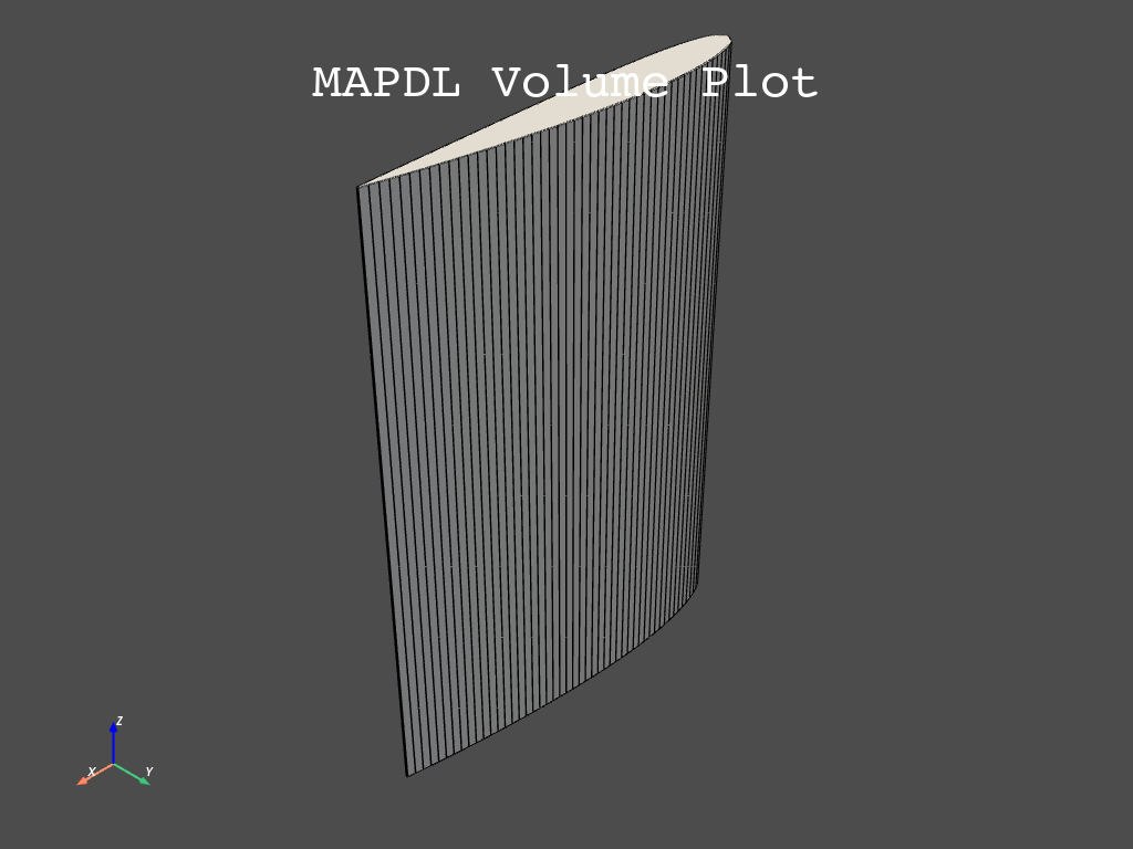
We are going to use the command mapdl.vdrag to create a volume by dragging
an area along a line.
help(mapdl.vdrag)
Help on method vdrag in module ansys.mapdl.core._commands.preproc.volumes:

vdrag(na1='', na2='', na3='', na4='', na5='', na6='', nlp1='', nlp2='', nlp3='', nlp4='', nlp5='', nlp6='', **kwargs) -> str method of ansys.mapdl.core.mapdl_grpc.MapdlGrpc instance
    Generate volumes by dragging an area pattern along a path.

    APDL Command: VDRAG

    Parameters
    ----------
    na1, na2, na3, . . . , na6
        List of areas in the pattern to be dragged (6 maximum if
        using keyboard entry).  If NA1 = ALL, all selected areas
        will be swept along the path.  A component name may also
        be substituted for NA1.

    nlp1, nlp2, nlp3, . . . , nlp6
        List of lines defining the path along which the pattern is
        to be dragged (6 maximum if using keyboard entry).  Must
        be a continuous set of lines.  To be continuous, adjacent
        lines must share the connecting keypoint (the end keypoint
        of one line must also be first keypoint of the next line).

    Returns
    -------
    str
        MAPDL command output.

    Notes
    -----
    Generates volumes (and their corresponding keypoints, lines,
    and areas) by sweeping a given area pattern along a
    characteristic drag path.  If the drag path consists of
    multiple lines, the drag direction is determined by the
    sequence in which the path lines are input (NLP1, NLP2, etc.).
    If the drag path is a single line (NLP1), the drag direction
    is from the keypoint on the drag line that is closest to the
    first keypoint of the given area pattern to the other end of
    the drag line.

    The magnitude of the vector between the keypoints of the given
    pattern and the first path keypoint remains constant for all
    generated keypoint patterns and the path keypoints.  The
    direction of the vector relative to the path slope also
    remains constant so that patterns may be swept around curves.
    Lines are generated with the same shapes as the given pattern
    and the path lines.

    Keypoint, line, area, and volume numbers are automatically
    assigned (beginning with the lowest available values
    [NUMSTR]).  Adjacent lines use a common keypoint, adjacent
    areas use a common line, and adjacent volumes use a common
    area.  For best results, the entities to be dragged should be
    orthogonal to the start of the drag path.  Drag operations
    that produce an error message may create some of the desired
    entities prior to terminating.

    If element attributes have been associated with the input area
    via the AATT command, the opposite area generated by the VDRAG
    operation will also have those attributes (i.e., the element
    attributes from the input area are copied to the opposite
    area).  Note that only the area opposite the input area will
    have the same attributes as the input area; the areas adjacent
    to the input area will not.

    If the input areas are meshed or belong to a meshed volume,
    the area(s) can be extruded to a 3-D mesh.  Note that the NDIV
    argument of the ESIZE command should be set before extruding
    the meshed areas.  Alternatively, mesh divisions can be
    specified directly on the drag line(s) (LESIZE).  See the
    Modeling and Meshing Guide for more information.

    You can use the VDRAG command to generate 3-D interface
    element meshes for elements INTER194 and INTER195. When
    generating interface element meshes using VDRAG, you must
    specify the line divisions to generate one interface element
    directly on the drag line using the LESIZE command.  The
    source area to be extruded becomes the bottom surface of the
    interface element. Interface elements must be extruded in what
    will become the element's local x direction, that is, bottom
    to top.

    Examples
    --------
    Create a square with a hole in it and drag it along an arc.

    >>> anum0 = mapdl.blc4(0, 0, 1, 1)
    >>> anum1 = mapdl.blc4(0.25, 0.25, 0.5, 0.5)
    >>> aout = mapdl.asba(anum0, anum1)
    >>> k0 = mapdl.k("", 0, 0, 0)
    >>> k1 = mapdl.k("", 1, 0, 1)
    >>> k2 = mapdl.k("", 1, 0, 0)
    >>> l0 = mapdl.larc(k0, k1, k2, 2)
    >>> output = mapdl.vdrag(aout, nlp1=l0)
    >>> print(output)
    DRAG AREAS
      3,
    ALONG LINES
      9
First, let’s define the length we are going to use to drag the area along.
lenght_wing = 1.5  # [m] MAPDL is unit agnostic.

k0 = mapdl.k("", 0, 0, 0)
kz = mapdl.k("", 0, 0, lenght_wing)

ldrag = mapdl.l(k0, kz)
Create the volume
vol0 = mapdl.vdrag("all", nlp1=ldrag)
Let’s check the results
mapdl.vplot()
Finite element definition#
As you all know, finite element approaches split the domains into “finite elements” where you solve your equations in their quadrature points. Therefore, we need to define how that domain split is going to be performed, aka “choosing element type”.
# Defining element type
mapdl.et(1, "SOLID187")
1
Here we could also define other element options using the mapdl.keyopt
command.
Material definition#
Let’s define the material our wing is made off. We are going to choose steel in its simplest configuration (elastic linear material). But you could define other parameters (plasticity, fatige, viscoelasticity, etc).
# Define a material (nominal steel in SI)
mapdl.mp("EX", 1, 210e9)  # Elastic moduli in Pa (kg/(m*s**2))
mapdl.mp("DENS", 1, 7800)  # Density in kg/m3
mapdl.mp("NUXY", 1, 0.3)  # Poisson's Ratio
MATERIAL 1 NUXY = 0.3000000
Mesh Generation#
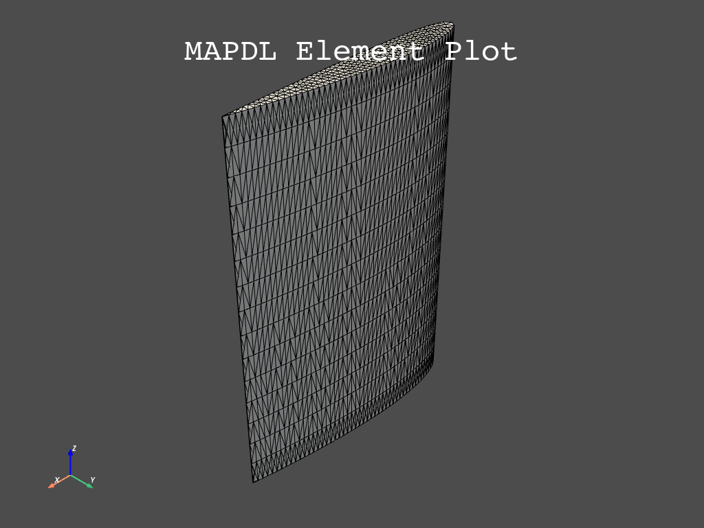
Let’s finally split the domain:
maximum_element_size = 1 / 10
mapdl.esize(maximum_element_size)

mapdl.vmesh("all")  # Mesh
GENERATE NODES AND ELEMENTS   IN  ALL  SELECTED VOLUMES
  Sharp angle warning:
    triangle facet defined at line  199 forms an angle of 1.4 degrees
    with facet at line  197
  Sharp angle warning:
    triangle facet defined at line  199 forms an angle of 1.4 degrees
    with facet at line  197
  Sharp angle warning:
    triangle facet defined at line  199 forms an angle of 1.4 degrees
    with facet at line  197
  Sharp angle warning:
    triangle facet defined at line  201 forms an angle of 1.4 degrees
    with facet at line  197
  Sharp angle warning:
    triangle facet defined at line  201 forms an angle of 1.4 degrees
    with facet at line  199
  Sharp angle warning:
    triangle facet defined at area   51 forms an angle of 1.4 degrees
    with facet at area   50
  Sharp angle warning:
    triangle facet defined at area   51 forms an angle of 1.4 degrees
    with facet at area   50
  Sharp angle warning:
    triangle facet defined at area   51 forms an angle of 1.4 degrees
    with facet at area   50
  Sharp angle warning:
    triangle facet defined at area   51 forms an angle of 1.4 degrees
    with facet at area   50
  Sharp angle warning:
    triangle facet defined at line  201 forms an angle of 1.4 degrees
    with facet at line  199
  Sharp angle warning:
    triangle facets defined at line  199 form an angle of 1.4 degrees
   etc... (see error file)

 *** WARNING ***                         CP =       5.949   TIME= 10:48:56
 68 angles less than 2.5 degrees found in triangle facets of volume 1,
 with smallest angle = 1.4 degrees.  Poor element quality or mesh
 failure may result.  A smaller element size specification may give
 better results.

 NUMBER OF VOLUMES MESHED   =         1
 MAXIMUM NODE NUMBER        =     16044
 MAXIMUM ELEMENT NUMBER     =      8879

 ------------------------------------------------------------------------------
            <<<<<<          SHAPE TESTING SUMMARY           >>>>>>
            <<<<<<       FOR NEW OR MODIFIED ELEMENTS       >>>>>>
 ------------------------------------------------------------------------------
                    --------------------------------------
                    |  Element count      8879 SOLID187  |
                    --------------------------------------

  Test                Number tested  Warning count  Error count    Warn+Err %
  ----                -------------  -------------  -----------    ----------
  Aspect Ratio               8879             77             0         0.87 %
  Maximum Angle              8879             59             0         0.66 %
  Jacobian Ratio             8879              0             0         0.00 %

  Any                        8879            107             0         1.21 %
 ------------------------------------------------------------------------------

 *** WARNING ***                         CP =       6.167   TIME= 10:48:56
 Shape testing revealed that 107 of the 8879 new or modified elements
 violate shape warning limits.  To review test results, please see the
 output file or issue the CHECK command.
Let’s check the results:
mapdl.eplot()
Boundary Conditions Definition#
Let’s fix the nodes at the origin to not move.
mapdl.nsel("s", "loc", "z", 0)
mapdl.d("all", "all", 0)
SPECIFIED CONSTRAINT UX   FOR SELECTED NODES            1 TO       16044 BY           1
 REAL=  0.00000000       IMAG=  0.00000000
 ADDITIONAL DOFS=  UY    UZ
Wind Excitation#
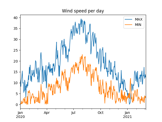
Let’s apply an excitation to our wing. However, we don’t really know what wind speed to apply, so let’s pull some online data first.
We are going to retrieve some data from NASA regarding the wind speed at Ansys Madrid office in Paseo de la Castellana.

Paseo de la Castellana Ansys office (Madrid). Yes, we love coffee.#
From: https://power.larc.nasa.gov/data-access-viewer/
import json

import pandas as pd
import requests

latitude, longitude = (40.447488, -3.691763)
parameters = ["T2M_MAX", "T2M_MIN"]

base_url = r"https://power.larc.nasa.gov/api/temporal/daily/point?parameters={parameters}&community=RE&longitude={longitude}&latitude={latitude}&start=20200101&end=20210305&format=JSON"
api_request_url = base_url.format(
    longitude=longitude, latitude=latitude, parameters=",".join(parameters)
)  # Another way to format f-strings!

response = requests.get(url=api_request_url, verify=True, timeout=30.00)

content = json.loads(response.content.decode("utf-8"))
df = pd.DataFrame(content["properties"]["parameter"])

df.columns = ["MAX", "MIN"]  # renaming columns
df = df.set_index(
    pd.to_datetime(df.index, format="%Y%m%d")
)  # Formatting dataframe index as date.
Let’s see the data
df.head()
and describe it…
We see there are negative wind speed, probably because of the direction, since we are not interested in direction, only magnitude, let’s use the absolute value then.
Let’s plot it…
_ = df.plot(title="Wind speed per day")
As we can see, the most frequent maximum speeds are:
_ = df["MAX"].hist(bins=20)
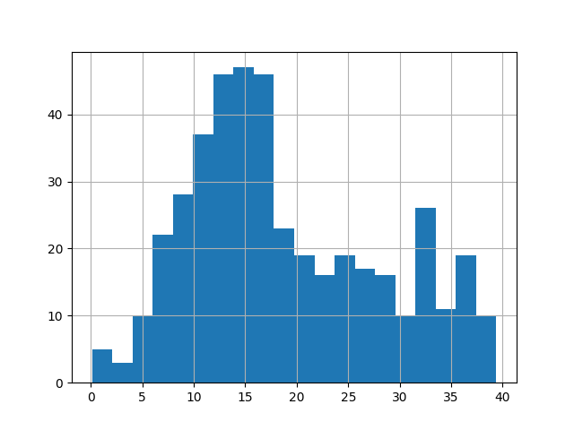
As we can see, we could stablish there are two main peaks, one at 15 m/s and another at 33 m/s.
Let’s generate some random wind signal with those speeds. We are going to do a superposition of harmonics:
amplitude = [15, 33]
frequencies = (
    np.array([10, 16]) * 2 * np.pi
)  # Typical wind frequencies range between 2 and 20 Hz
phase = np.random.random(size=len(frequencies)) * 2 * np.pi


def wind_speed(t):
    sum_ = 0
    for each_amp, each_w, each_phase in zip(amplitude, frequencies, phase):
        sum_ = sum_ + each_amp * np.cos(each_w * t + each_phase)
    return sum_


t = np.arange(0, 1, 0.01)

plt.plot(t, wind_speed(t))
plt.show()
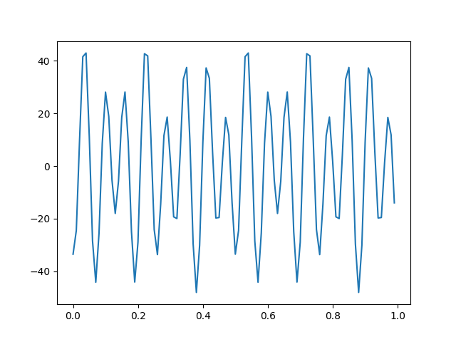
To apply these velocities, we are going instead to convert it to acceleration using the following equation:
where:
ais accelerationwis frequencyvis velocity
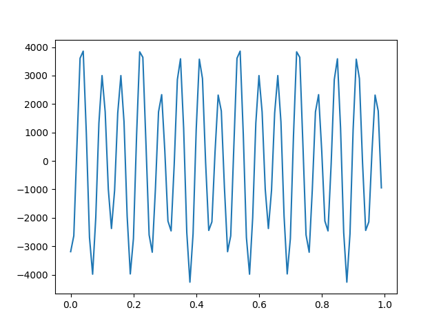
Now let’s use that in our analysis
We are going to apply a global acceleration using mapdl.acce.
help(mapdl.acel)
Help on method acel in module ansys.mapdl.core._commands.solution.inertia:

acel(acel_x='', acel_y='', acel_z='', **kwargs) method of ansys.mapdl.core.mapdl_grpc.MapdlGrpc instance
    Specifies the linear acceleration of the global Cartesian reference

    APDL Command: ACEL
    frame for the analysis.

    Parameters
    ----------
    acel_x, acel_y, acel_z
        Linear acceleration of the reference frame along global Cartesian
        X, Y, and Z axes, respectively.

    Notes
    -----
    In the absence of any other loads or supports, the acceleration of the
    structure in each of the global Cartesian (X, Y, and Z) axes would be
    equal in magnitude but opposite in sign to that applied in the ACEL
    command. Thus, to simulate gravity (by using inertial effects),
    accelerate the reference frame with an ACEL command in the direction
    opposite to gravity.

    You can define the acceleration for the following analyses types:

    Static (ANTYPE,STATIC)

    Harmonic (ANTYPE,HARMIC), full or mode-superposition method

    Transient (ANTYPE,TRANS)

    Substructure (ANTYPE,SUBSTR).

    For all transient dynamic (ANTYPE,TRANS) analyses, accelerations are
    combined with the element mass matrices to form a body force load
    vector term. The element mass matrix may be formed from a mass input
    constant or from a nonzero density (DENS) property, depending upon the
    element type.

    For analysis type ANTYPE,HARMIC, the acceleration is assumed to be the
    real component with a zero imaginary component.

    Units of acceleration and mass must be consistent to give a product of
    force units.

    The ACEL command supports tabular boundary conditions (%TABNAME_X%,
    %TABNAME_Y%, and %TABNAME_Z%) for ACEL_X, ACEL_Y, and ACEL_Z input
    values (``*DIM``) as a function of both time and frequency for full
    transient and harmonic analyses.

    Related commands for rotational effects are CMACEL, CGLOC, CGOMGA,
    DCGOMG, DOMEGA, OMEGA, CMOMEGA, and CMDOMEGA.

    See Analysis Tools in the Mechanical APDL Theory Reference for more
    information.

    This command is also valid in /PREP7.

    Examples
    --------
    Set global y-acceleration to 9.81

    >>> mapdl.acel(acel_y=9.81)
Model solution#
mapdl.slashsolu()
mapdl.allsel()  # making sure all nodes and elements are selected.
mapdl.antype("TRANS")
mapdl.nsubst(carry="ON")

accelerations = acceleration(t)

for each_time, each_acceleration in zip(t[1:], accelerations):
    mapdl.time(each_time)
    mapdl.acel(acel_y=each_acceleration)
    mapdl.solve()
Post-processing#
Let’s see what we got. Let’s print the displacements for the first step.
mapdl.post1()
mapdl.set(1, 1)
mapdl.post_processing.nodal_displacement("all")
array([[ 0.00000000e+00,  0.00000000e+00,  0.00000000e+00],
       [ 0.00000000e+00,  0.00000000e+00,  0.00000000e+00],
       [ 0.00000000e+00,  0.00000000e+00,  0.00000000e+00],
       ...,
       [-2.25461341e-05,  4.01419365e-02,  4.04008850e-04],
       [-3.32841972e-05,  1.25655615e-02,  3.32471074e-04],
       [-4.27405267e-05,  1.06756207e-02,  3.81884332e-04]])
and let’s plot them
mapdl.post_processing.plot_nodal_displacement("y")
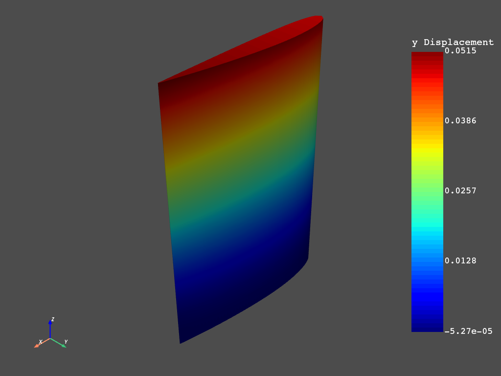
We can follow this approach to get the results at each step
For example let’s get the maximum principal stresses and where it happens:
i = 0
max_stress_per_step = []
elem_max_stress_per_step = []

for step in mapdl.post_processing.time_values:
    i += 1
    mapdl.set(i)
    stresses = mapdl.post_processing.element_stress("1")  # First principal stresses
    max_stress_per_step.append(stresses.max())
    elem_max_stress_per_step.append(stresses.argmax())

max_stress_per_step = np.array(max_stress_per_step)
elem_max_stress_per_step = np.array(elem_max_stress_per_step)

elem_ = mapdl.mesh.enum[elem_max_stress_per_step[max_stress_per_step.argmax()]]
time_ = mapdl.post_processing.time_values[max_stress_per_step.argmax()]

print(
    f"The maximum principal stress\n\tValue: {max_stress_per_step.max():0.2f} Pascals."
)
print(f"\tAt the element {elem_}.")
print(f"\tAt the time {time_}.")
The maximum principal stress
        Value: 3982711613.36 Pascals.
        At the element 5399.
        At the time 0.04.
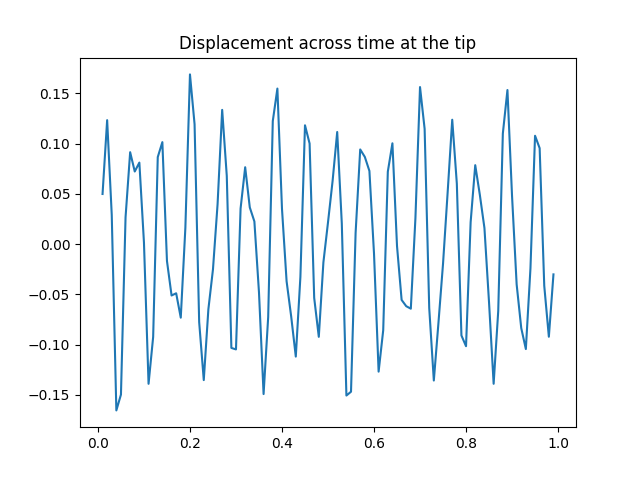
Post-processing time dependent results#
Let’s now check the displacement across time for a node in the tip
We can get the nodes max and min coordenates as:
Getting the displacement at the tip
item = "U"
comp = "Y"
nvar = 9

# node_uy = mapdl.get_nsol(node, item, comp)  # Available in 0.62.3
mapdl.nsol(nvar, node, item, comp)
mapdl.vget("temp_", nvar)

node_uy = mapdl.parameters["temp_"]
time = mapdl.post_processing.time_values

plt.plot(time, node_uy)
plt.title("Displacement across time at the tip")
plt.show()
Closing session#
Thank you all for your time and attention!
mapdl.exit()
Total running time of the script: ( 1 minutes 53.689 seconds)